Test Racks
What can our custom Test Racks do for your Medical, Automotive, Industrial Control or Aerospace product?

- Perform comprehensive, consistent and repeatable electrical testing
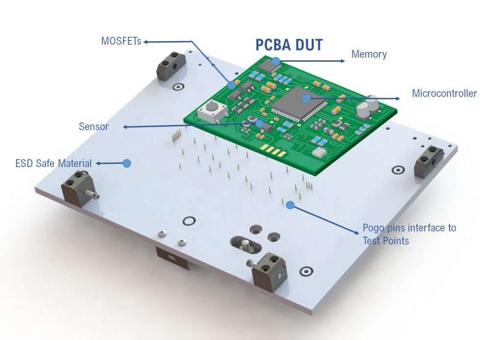
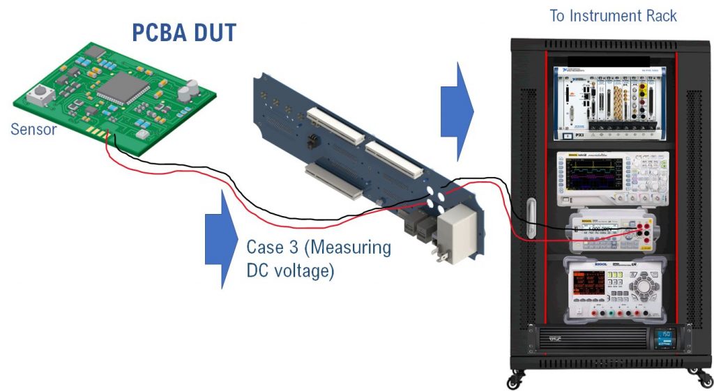
- Validate PCBA on-board measurements against NIST Calibrated test equipment
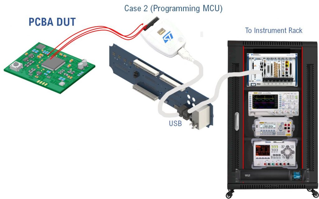
- Program processors and non-volatile memory; assign serial numbers
- Test single boards or electronic sub-assemblies
- Perform long-term, repetitive and controlled tests as part of HIL (Hardware-In-The-Loop) endurance testing
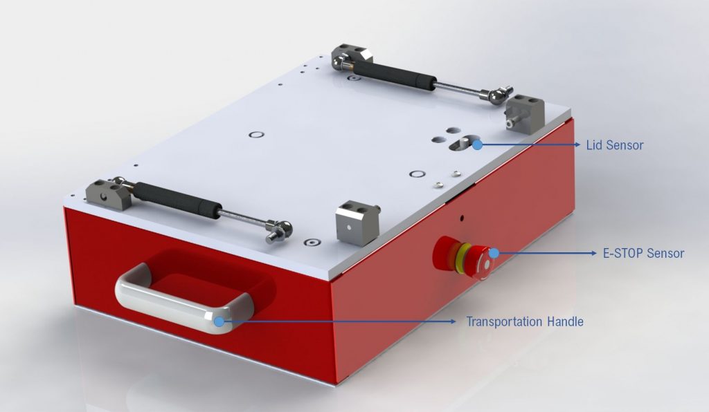
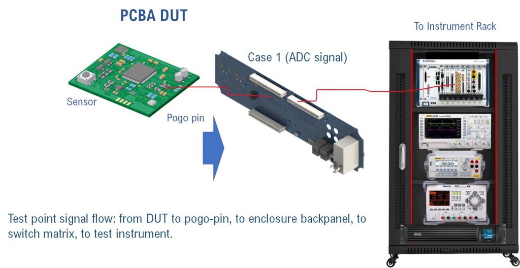
- Perform thousands of test cycles (internal counter, replaceable sprigged pogo-pins)
- High duplicability for parallel testing and increasing test volumes (Low->Med->High)
- Interfaces include USB, Ethernet, Serial, D-SUB, coax, legacy GPIB and custom headers
- Modular back plane Provides Flexibility, Ease of Use, scalability and Protection to Operator, DUT and Test equipment
- Improve the quality of your electronic products through Functional Testing (FT)
Test Architecture
In short, the overall test architecture of any test system comprises several key aspects:
▄ Matrix Switch Hardware
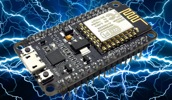
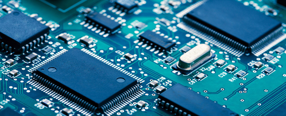
▄ PCBA Device Under Test (DUT)
▄ Interface to DUT
▄ Mass interconnect system
▄ Test Instruments (off-the shelf or PXI)
▄ Switch Hardware
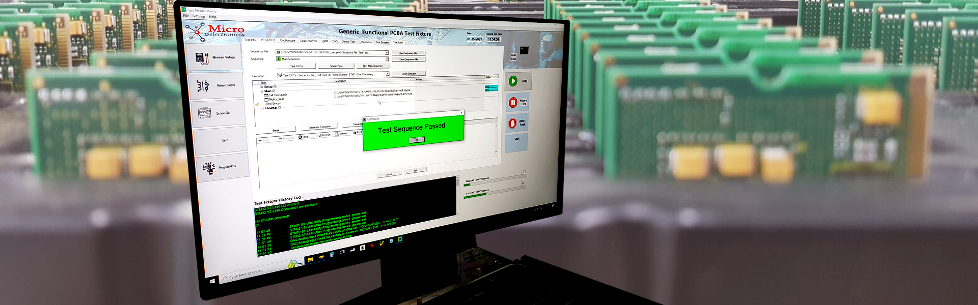
▄ Software running test sequence with final report storage
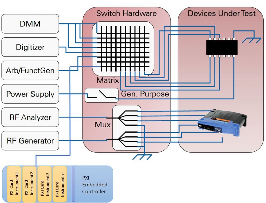
Our test-rack devices perform Automatic Functional Testing (or AFT) which differs from Flying-Probe Testing in many aspects. First, FPT is performed serially on every component of your PCBA, this is due to the fact that the flying probe is attached to a single X-Y-X mechanism which cannot test several test points simultaneously. Whereas AFT using “bed-of-nails” or pogo-pins can perform parallel testing; this is possible because the pogo pins are in contact all the time with the Device Under Test (DUT) and since there are multiple instruments inside the rack, the test software can be programmed to perform multiple measurements at once to expedite the test procedure and decrease testing time per unit.
Secondly, FPT is limited to testing component values on the PCBA. It is not intended to test the functionality of the circuit since the test is done with no power on the DUT. To better understand FPT, picture yourself with a multimeter testing every component on the board and taking note of the results on a notepad. The only difference is that the instrument is attached to a robotized mechanism. FPT does not tell you if the circuit performs well, only if it was correctly assembled with the right components. For this reason, Flying Probe Test cannot replace Functional Test Fixture during the production cycle of a PCBA.
An Automatic Functional Test fixture can download test fixture firmware inside the microcontroller(s) of the PCBA under test; this special firmware differs from the production one since it is developed with the purpose of interfacing with the Rack firmware to control and stress all aspects of the hardware. Once the DUT has been proven to pass all tests, the last step the AFT performs is to automatically program the Production Firmware on the device and get it ready for the final system test. This step usually comprises the programming of any EEPROM and/or FLASH memories and assigning serial numbers in firmware.
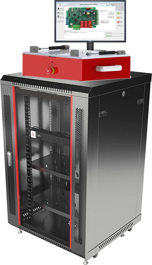
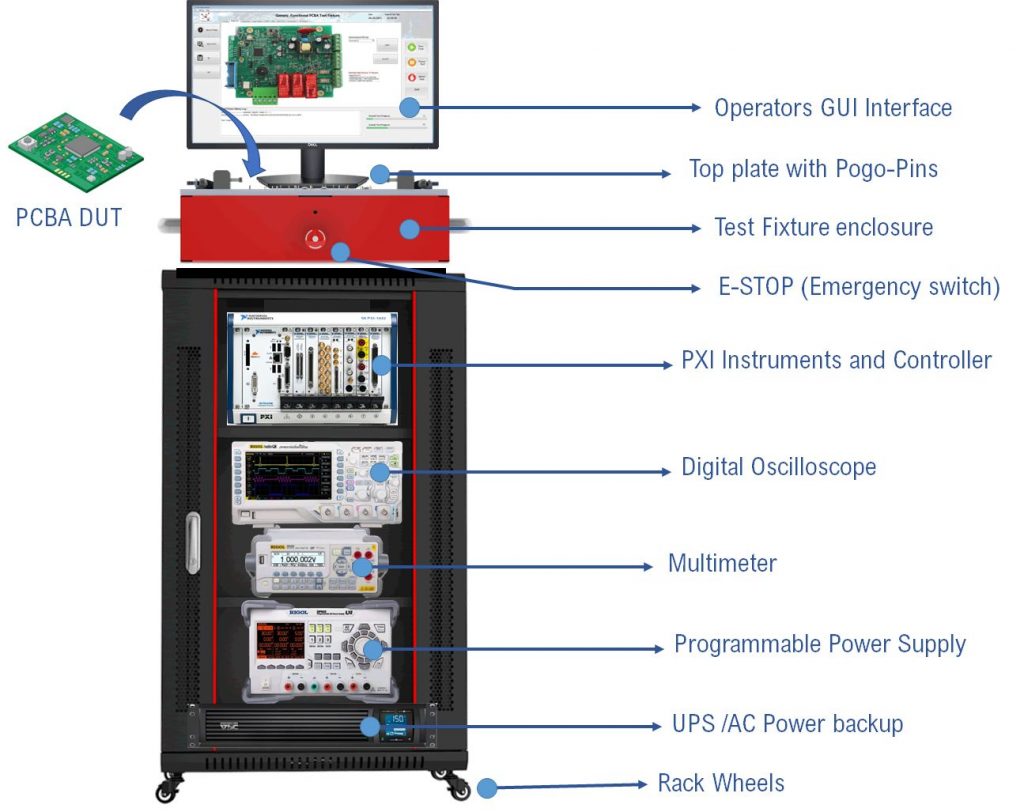
Our custom Test Rack Solution

We know electronic testing!
By working in several demanding industries, we have over the years developed systematic methods and procedures to expedite the verification, validation and testing of our electronic boards. This has included the development of Automated Test Fixtures to accelerate and improve the performance of our design cycle and quickly bridge from development (R&D) to electronics mass manufacturing.
Today, taking advantage of all that experience, we offer our customers our Apollo Test Rack (shown in Figure 3) which provides an almost “ready-to-go” test platform for many electronic boards. Our system is fully customizable depending on your test needs.
Call us now to schedule your FREE consultation about your electronic Automated Testing needs!
engineering@microelectronicos.com ____ Ph. (949) 2261622