Monthly Archives: April 2017

Controlling a high torque stepper Motor with Arduino
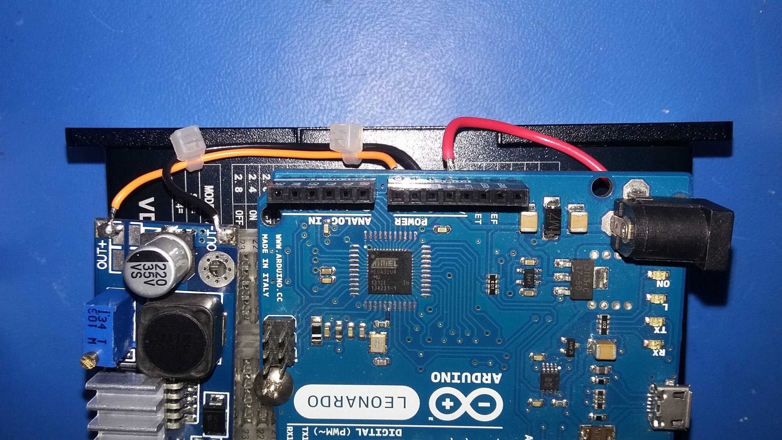
Check out our most recent project: Controlling a Stepper Motor (Nema23) and a Motor Driver M542T with Arduino. The motor driver uses a +24VDC power supply (2.5A) to provide high torque and speed to the stepper. The Arduino generates the control signals to control the driver (M542T). Basically two signals are being driven on the MT542T: Direction (DIR) and Speed (PUL). The PUL signal is PWM with the duty cycle depends on the current required by the motor. For this application the frequency of the PWM was chosen to be 5KHz (T= 200 uSec).


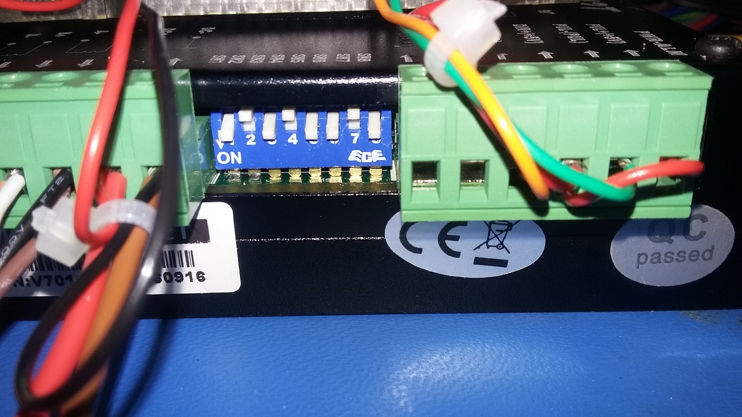
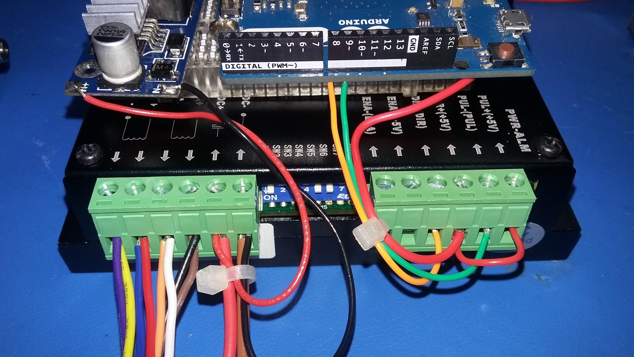
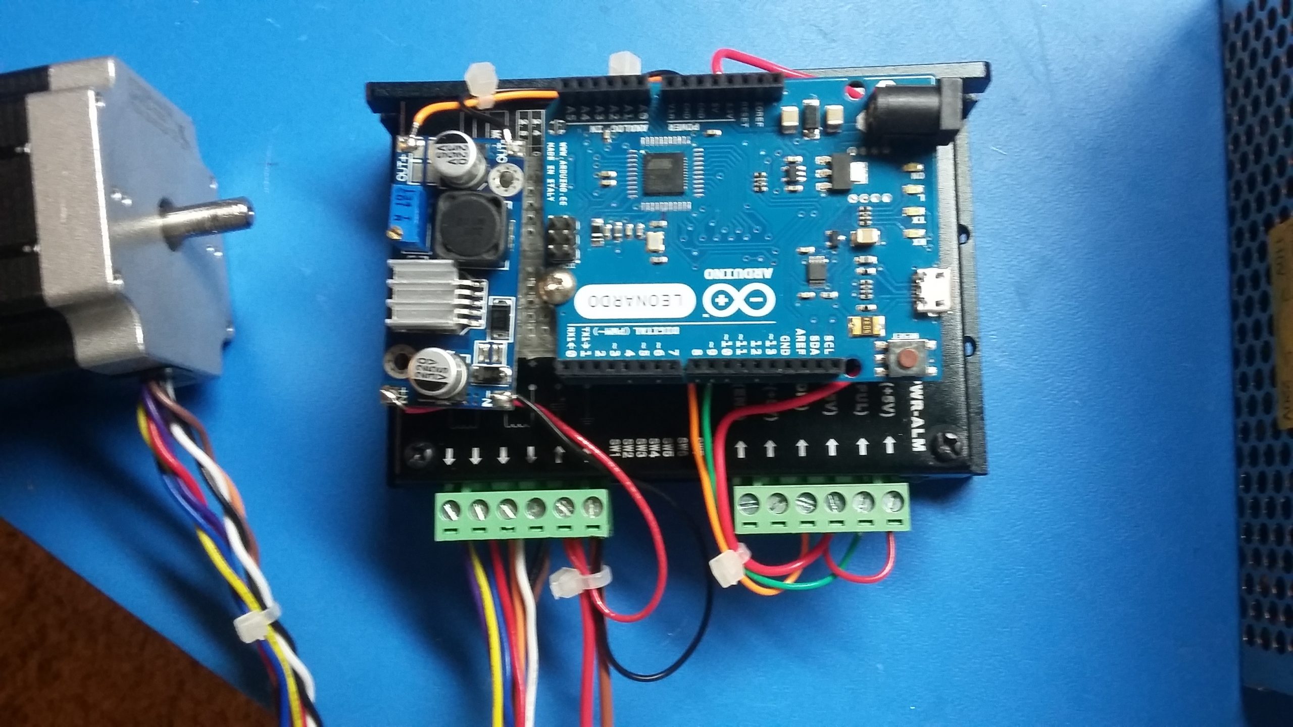
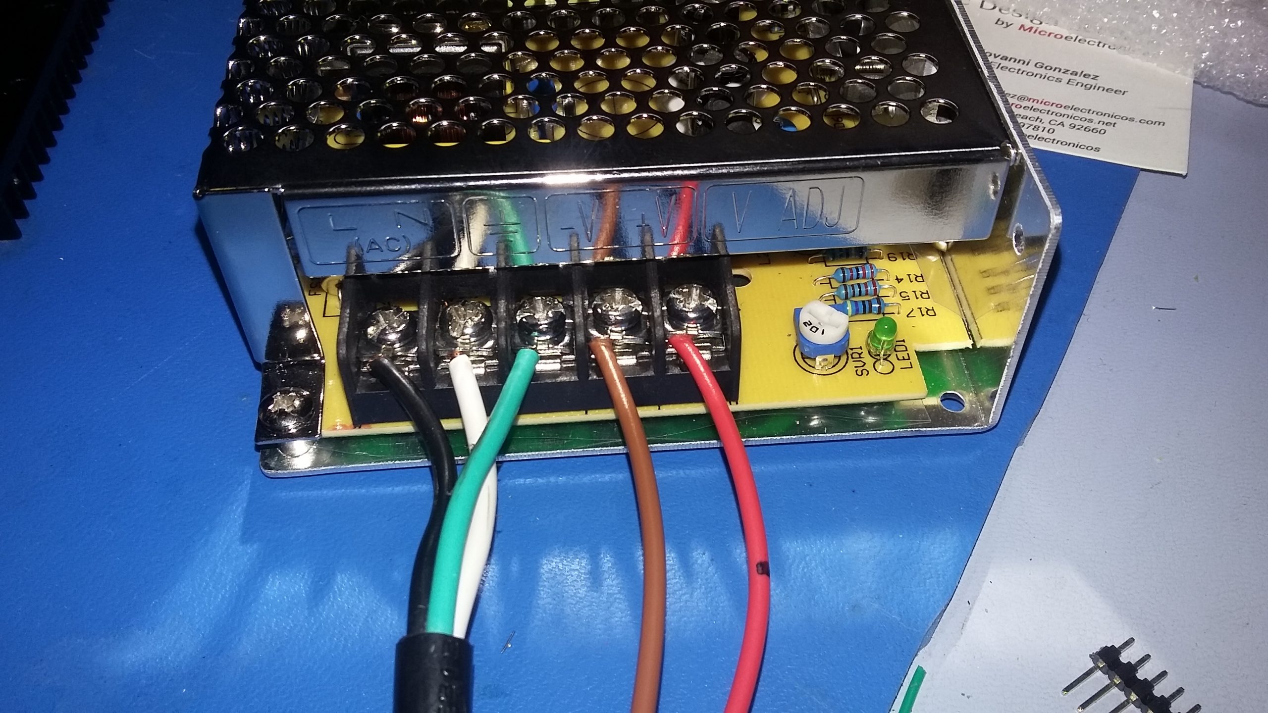
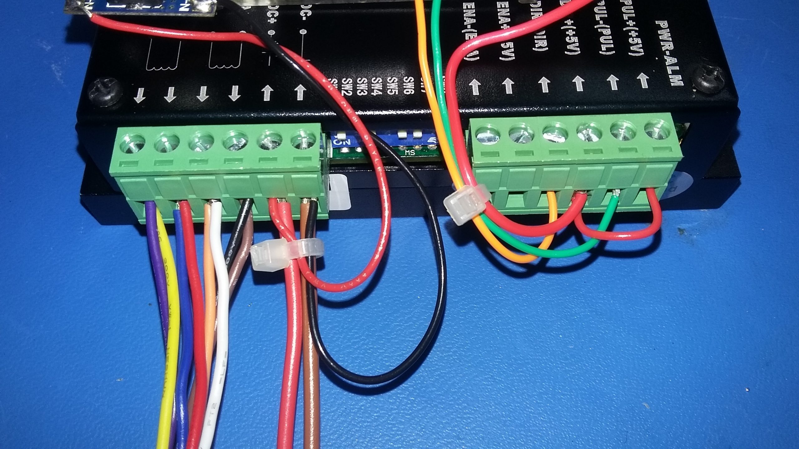
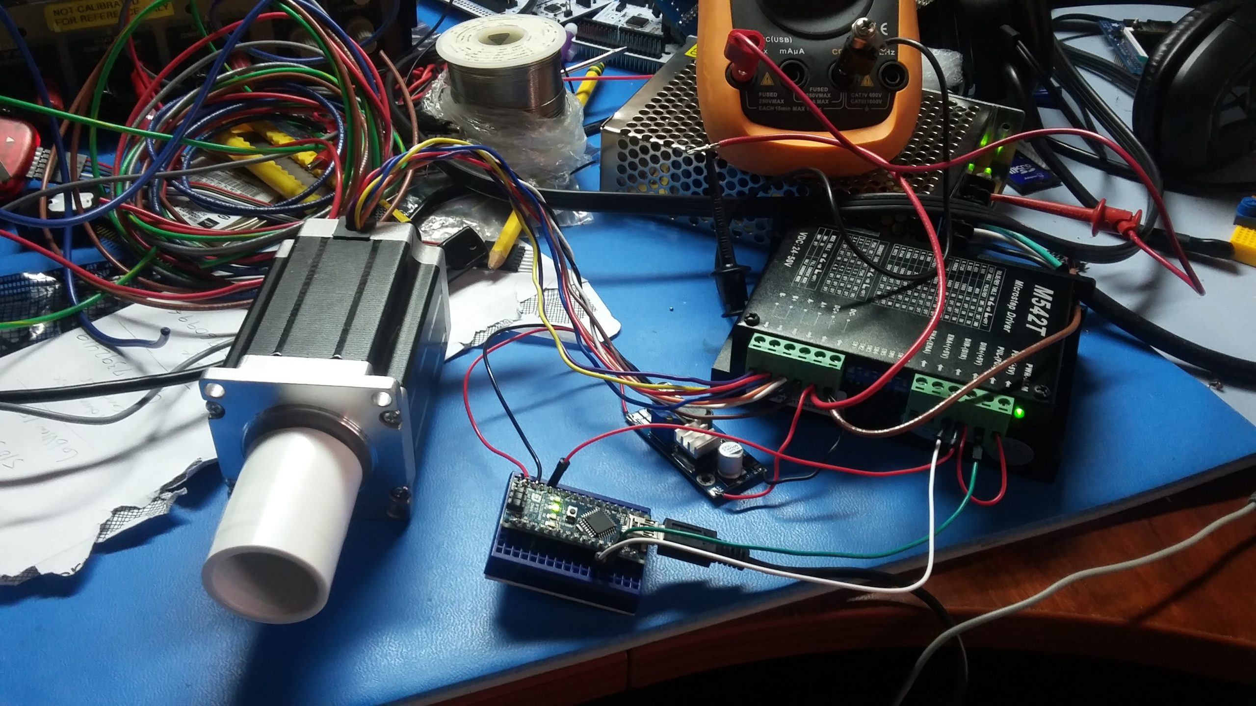
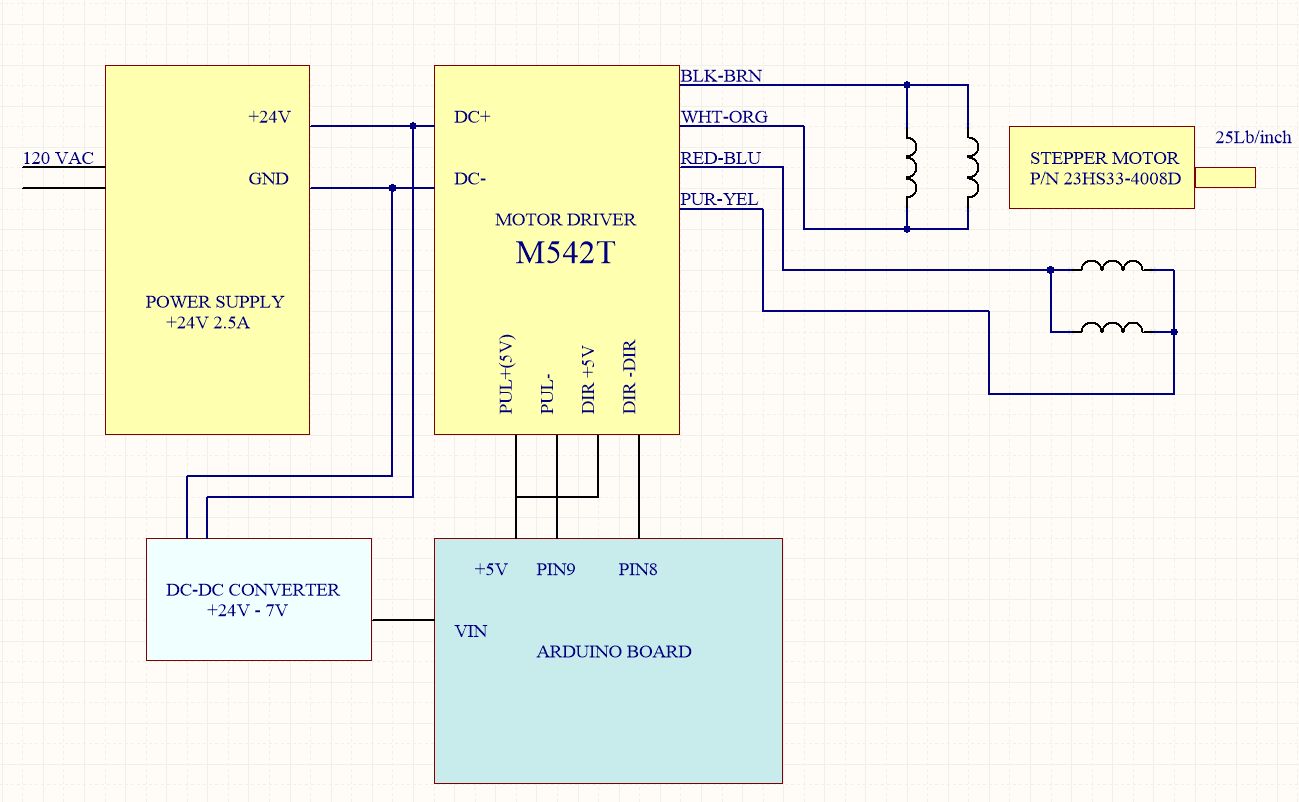
The electrical schematic we used is the following (see diagram below). You can use a different power supply (more current capability) if you require more torque in your application. In our case, the motor windings have been wired in a bipolar parallel configuration which provides a high torque at high speeds since it presents the lowest inductance (and resistance to the current). With this configuration the motor can provide up to 2.83N.m/400 oz-in (25 Lb per inch) and each phase can draw up to 5.66 A.
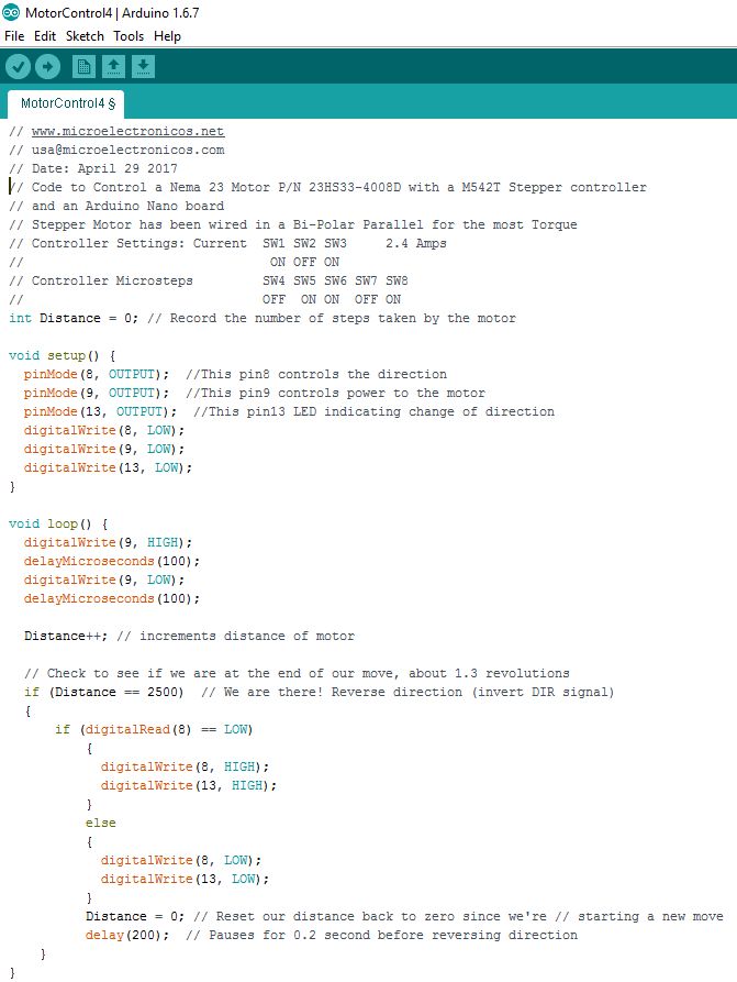
You can see the Arduino code below (any Arduino board can be used: Uno/Leonardo/Nano/Mega/Mini, or similar)
-
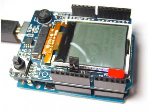 LCD Shield Monocromatic for Arduino
$80.00
LCD Shield Monocromatic for Arduino
$80.00
-
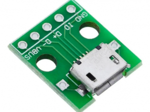 Adapter Micro USB
$45.00
Adapter Micro USB
$45.00